Understanding How InterVLAN Routing Works
Network devices in different VLANs cannot communicate with one another without a router to route traffic between the VLANs. In most network environments, VLANs are associated with individual networks or subnetworks.
For example, in an IP network, each subnetwork is mapped to an individual VLAN. In a Novell IPX network, each VLAN is mapped to an IPX network number. In an AppleTalk network, each VLAN is associated with a cable range and AppleTalk zone name.
Configuring VLANs helps control the size of the broadcast domain and keeps local traffic local. However, when an end station in one VLAN needs to communicate with an end station in another VLAN, interVLAN communication is required. This communication is supported by interVLAN routing. You configure one or more routers to route traffic to the appropriate destination VLAN.
shows a basic interVLAN routing topology. Switch A is in VLAN 10 and Switch B is in VLAN 20. The router has an interface in each VLAN.
Figure 3-1 Basic InterVLAN Routing Topology
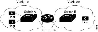
When Host A in VLAN 10 needs to communicate with Host B in VLAN 10, it sends a packet addressed to that host. Switch A forwards the packet directly to Host B, without sending it to the router.
When Host A sends a packet to Host C in VLAN 20, Switch A forwards the packet to the router, which receives the traffic on the VLAN 10 interface. The router checks the routing table, determines the correct outgoing interface, and forwards the packet out the VLAN 20 interface to Switch B. Switch B receives the packet and forwards it to Host C.
shows another common scenario, interVLAN routing over a single trunk connection to the router. The switch has ports in multiple VLANs. InterVLAN routing is performed by a Cisco 7505 router connected to the switch through a full-duplex Fast Ethernet trunk link.
Figure 3-2 InterVLAN Routing Over a Single Trunk Link

Multiple subinterfaces are configured on the physical Fast Ethernet router interface, one for each VLAN supported on the trunk. IntraVLAN traffic (traffic with the source and destination host in the same VLAN) is handled entirely by the switch.
InterVLAN traffic is sent across the trunk to the router. The router checks the routing table, determines the outgoing subinterface (destination VLAN), and sends the traffic back over the trunk to the switch, where it is forwarded out the appropriate switch port.
Configuring VTP and VLANs on the Switch
To successfully configure a router for interVLAN routing, you must configure VTP and create and configure VLANs on the switch.
Note ![]() This section describes the basics of VTP and VLAN configuration. For detailed information on configuring VTP and VLANs, see the Software Configuration Guide for your switch.
This section describes the basics of VTP and VLAN configuration. For detailed information on configuring VTP and VLANs, see the Software Configuration Guide for your switch.
To configure VTP and VLANs on the switch, perform this task in privileged mode:
This example shows how to configure VTP, create two VLANs, and assign switch ports to those VLANs:
Console> (enable) set vtp mode server
VTP domain modified
Console> (enable) set vtp domain Corp_Net
VTP domain Corp_Net modified
Console> (enable) set vlan 100
Vlan 100 configuration successful
Console> (enable) set vlan 200
Vlan 200 configuration successful
Console> (enable) set vlan 100 3/1-12
VLAN 100 modified.
VLAN 1 modified.
VLAN Mod/Ports
---- -----------------------
100 1/1-2
3/1-12
Console> (enable) set vlan 200 3/13-24
VLAN 200 modified.
VLAN 1 modified.
VLAN Mod/Ports
---- -----------------------
200 1/1-2
3/13-24
Console> (enable)
Basic Router Configuration Tasks
These sections describe basic router configuration tasks you need to understand before you configure interVLAN routing:
•![]() Accessing Configuration Mode on the Router
Accessing Configuration Mode on the Router
•![]() Viewing and Saving the Router Configuration
Viewing and Saving the Router Configuration
•![]() Bringing Up a Router Interface
Bringing Up a Router Interface
Accessing Configuration Mode on the Router
To access configuration mode on the router, perform this task, beginning in normal EXEC mode:
Viewing and Saving the Router Configuration
To view and save the configuration after you make changes, perform this task in privileged EXEC mode:
Bringing Up a Router Interface
In some cases, a router interface might be administratively shut down. You can check the status of an interface using the show interface command
Source Cisco.com
Nema komentara:
Objavi komentar